
Introduction
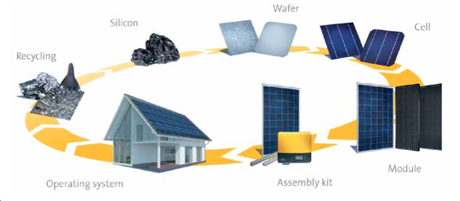
As one of the largest and most established vertically integrated photovoltaic (PV) manufacturers on the planet, SolarWorld is intimately involved with every step of the solar PV value chain from raw silicon to installed systems to end of life recycling. This complete knowledge base combined with our extensive history provide the critical insight required to lead the solar industry on technical topics.
The purpose of this paper is to discuss the mechanical design of photovoltaic systems for wind and snow loads in the United States, and provide guidance using The American Society of Civil Engineers (ASCE) Minimum Design Loads for Buildings and Other Structures, ASCE 7-05 and ASCE 7-10 as appropriate. With the introduction of the ASCE 7-10, there are two potential design principles used for calculating wind and snow loads for PV systems in the U.S. until all state building codes have transitioned to ASCE 7-10. This paper will show how to calculate for wind and snow loads using both design principles.
SolarWorld modules have been tested according to UL and IEC standards and the maximum design loads for various mounting methods are provided in the Sunmodule User Instruction guide. Once we have gone through the sample calculations and have the applicable wind and snow loads, we will compare them to SolarWorld’s higher mechanical load capacities to ensure that the Sunmodule solar modules are in compliance.
The design methodology in this document has been third party reviewed. Please see certified letter at the end of this document for more details.
|
Figure 1. A typical rooftop solar installation. U.S. model building codes have used ASCE 7-05 as the basis for several years, which largely follows the design principles of Allowable Stress Design. Recently ASCE 7-10 was published and has become the basis for the 2012 series of the International Codes (I-Codes). ASCE 7-10 represents a shift in design principles toward Load Resistance Factor Design. A few states have already adopted the 2012 International Building Code 2012 (IBC) that includes references to ASCE 7-10 and, for the first time, specifically mentions PV systems. There are several key differences between these two versions |
|
Below are the portions of the code that will be referenced in the sample calculations: iBc 2012 (asce 7-10) code references 1509.7.1 Wind resistance. Rooftop mounted pho- tovoltaic systems shall be designed for wind loads for component and cladding in accordance with Chapter 16 using an effective wind area based on the dimensions of a single unit frame. 1603.1.4 Wind Design data. The following information related to wind loads shall be shown, regardless of whether wind loads govern the design of the lateral force resisting system of the structure: 1) Ultimate design wind speed, V 2) Risk category 5) Component and cladding 1608.1 Design snow loads shall be determined in accordance with Chapter 7 of ASCE 7, but the design roof load shall not be less than that determined by section 1607. 1609.1.1 Determination of wind loads. Wind loads on every building or structure shall be determined in accordance with Chapter 26 to 36 of ASCE 7 or provisions of the alternate all-heights method in section 1606.6. 1609.4.1 Wind Directions and Sectors. For each selected wind direction at which the wind loads are to be evaluated, the exposure of the building or structure shall be determined for the two upwind sectors extending 45 degrees either side of the selected wind direction. The exposures in these two sectors shall be determined in accordance with Section 1609.4.2 and 1609.4.3 and the exposure resulting in the highest wind loads shall be used to represent wind from that direction. iBc 2009 (asce 7-05) code references 1608.1 Design snow loads shall be determined in accordance with Chapter 7 of ASCE 7, but the design roof load shall not be less than that determined by Section 1607. 1603.1.4 Wind Design Data 1) Basic wind 1609.1.1 Wind loads on every building or structure shall be determined in accordance with Chapter 6 of ASCE 7. Table 1609.3.1, which converts from 3-second gusts to fastest-mile wind speeds. 1609.4.1 Wind Directions and Sectors
1609.4.2 Surface Roughness Categories closely spaced obstructions. 2) Surface roughness C: Open terrain with few obstructions (generally less than 30 feet), flat open country, grasslands, water surfaces in hurricane- prone regions. 3) Surface roughness D: Flat areas and water surfaces outside of hurricane prone regions, smooth mud flats, salt flats, unbroken ice. |
|
|
|
For more information, please contact your Greentech Renewables sales representative at 800-409-2257 or apply for dealer pricing online.
|