When designing a PV system that is tilted or ground mounted, determining the appropriate spacing between each row can be troublesome or a downright migraine in the making. However, it is essential to do it right the first time to avoid accidental shading from the modules ahead of each row. This can lead to underperforming systems and angry customers. No one wants to have that. The same can be said about overcompensation, too. Think of how many more kWs you could have had. This article will get you started on the right foot with a simple and fast process to get you out in the field faster with excellent results.
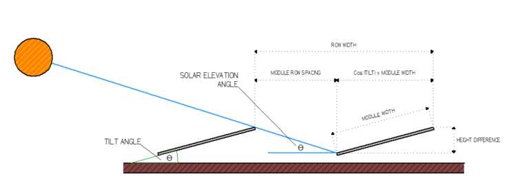
The first step in calculating the inter-row spacing for your modules is to calculate the height difference from the back of the module to the surface. To do that, follow this calculation below:
Height Difference = Sin (Tilt Angle) x Module Width
***Make sure you’re calculating in degrees, not radians***
In this case, I am using a SolarWorld module with a width of 39.41 inches at a tilt angle of 15º.
Height Difference = Sin (15) x 39.41
Height Difference = 10.2” rounded down to 10”
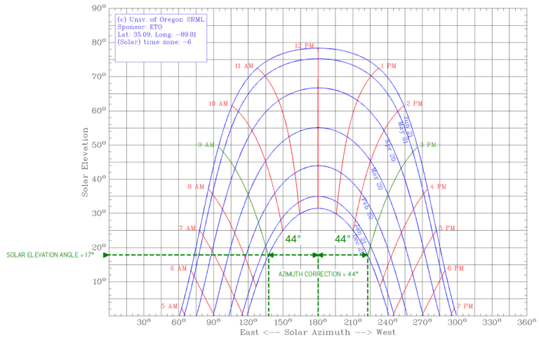
To calculate the Module Row Spacing, we need to hop over to a sun chart path program to determine our Sun Elevation Angle. You will enter your site's zip code, or to be more precise, you should enter the latitude and longitude of the location for more accurate results.
When you get your results, it will look something like this:

In this example, I picked a 9 AM to 3 PM window during the winter solstice for the worst-case scenario. You may opt for a less stringent case to suit your needs. I chose this example because some utilities require the 9 AM-3 PM window when offering rebates for customer-owned PV systems.
From the chart, you see that I have highlighted this window and drawn a horizontal line out to the left of the chart to narrow in on the Solar Elevation Angle at those times. I estimate a 17º angle, which I will use next to determine the Module Row Spacing using the formula below.
- Module Row Spacing = Height Difference / Tan (17)
- Module Row Spacing = 10 / Tan (17)
- Module Row Spacing = 32.7” rounded up to 33”
There you have it! The inter-row spacing between the trailing edge of the first row of modules and the leading edge of the next row needs to be 33”.
Just kidding…
We’re not done yet, and you’ll be glad you kept reading along…
The next thing we must do is account for the Azimuth angle and use that figure to apply that to another formula. Take a look again at the example below; you’ll see that I have drawn two vertical reference lines down from each time reference. The difference between South going in either direction turns out to be 44º, and we will use this in the following formula to determine the Minimum Module Row Spacing!
- Minimum Module Row Spacing = Module Row Spacing x Cos (Azimuth Correction Angle)
- Minimum Module Row Spacing = 33 x Cos (44)
- Minimum Module Row Spacing = 23.7” rounded up to 24”
Hey, you just gained an extra 9” for every row in your system! On cramped roofs or large commercial systems, that can make all the difference. Put another way, in this scenario, we could potentially increase the system size by 27%! What do you think about that?
And one last thing….
This last calculation is just a bonus and can help you layout your array in CAD a bit easier. The following formula gives you the distance from the trailing edge of one row to the trailing edge of the subsequent row or your Row Width.
- Row Width = Minimum Module Row Spacing + Cos (Tilt Angle) x Module Width
- Row Width = 24 + Cos (15) x 39.41
- Row Width = 62”
Now, go break out the TI-86 and put in some fresh batteries; I think you’ll enjoy figuring out the inter-row spacing for all your tilted or ground-mounted PV systems. Have fun!
If you have any further questions or inquiries, our helpful team at Greentech Renewables Design Services is here to help. Reach out today!


Comments
Could you make a couple of plug-in formulas for this calculation?
Hello. We don't typically send plug-in formulas within web pages, but the article does present some obvious formulas that you can apply to your particular application. That being said if you need engineering support, we are very glad to help address any issues you may have. Just let me know. Thanks again.
Good write up, Does this equation for determining row width hold good for single axis tracked panel rows which run north south.
The panels in each row tilt maximum +55/-55 towards the sun at sunrise and sunset.
Applying this height difference becomes 32.28 =32, module spacing =105, minimum module spacing =75
applying this in the last equation the row width comes to 97.6, is this correct or am I missing something when considering single axis tracking.
Regarding my earlier comment on single axis tracker, I realised that the azimuth correction will not apply if the location is close to the equator, please advise
Hello. Thank you for your questions. Here are our thoughts: Height Difference = 32.28”, Module Row Spacing = 105.59”, Minimum Row Spacing = 75.96”, and Trailing Edge Spacing 98.56”. This is the correct way to review ground mount layouts even for single-axis trackers when accounting for maximum tilt angles as this comment suggests. This response may or may not provide you all the information that you need. Happy to connect you with a Sales Person and/or Engineering support if you need more information. Please just contact us and provide more information on how we can support you. Thanks.
Do I need to consider azimuth correction if the solar panels are facing South direction. i.e 180deg. ? I guess azimuth correction is needed only if the panels are not facing south (considering location in India)?
This formula is based on facing due south. If not facing due south you’ll add a complex angle and slightly different width measurement that requires a bit more consideration for row spacing.
Please contact us and provide more information on how we can support you. Thanks.
Location : Robinvale, Victoria, Australia
Tilt Angle : 20 degree facing North
Panel dimension : 2015* 1000* 35 mm
Panel will be placed in portrait mode so based on this equation module width will be 2015 mm.
What will be the best and optimum inter row spacing ( Minimum to avoid shading issue)
Thank you for your comment. Calculating optimum inter-row spacing is explained in this article. I hope that it answers your questions but if you have additional specific questions please let us know and we can work to assist you. Thanks again.
Thanks so much for this write-up, it has been extremely useful.
One thing I might need help with: I have mapped all the calculations in Excel and transformed them into a dynamic graph. Everything works wonderfully, however, as soon as I include the 'Azimuth correction angle', the sun does not fully reach the 2nd row of panels. Any advice you could give?
Good afternoon. Its really hard to decipher what the issue is with your calculations/graph. One thought is that the article mentions, "Make sure you’re calculating in degrees, not radians" Hope that is helpful. Feel free to reach out to our contact us page and we can connect you to a design professional so they can talk to more about the issue. Thanks again.
I have calculated values as exactly the same as it is mentioned above because my sun chart is almost the same. My question is how did you predict the solar elevation angle 17 degree and azimuth correction angle 44 degree because one degree change has a huge impact on the final value. How to divide intervals correctly?
The Solar Elevation Angle and Azimuth Correction angle in our example are the products of selecting “a 9 AM to 3 PM window during the winter solstice for the worst-case scenario”. Once you’ve selected the window you’ll find the Solar Elevation angle by drawing the line to the corresponding angle on the Solar Elevation axis. The Azimuth Correction angle is calculated by finding the difference of 180 and the corresponding azimuth from the point you have selected in your window by drawing a line to the Solar Azimuth axis(per the example 180-136=44 & 224-180=44). As the article states you may opt for a less stringent case depending on their needs. Thank you for your question and let us know if you need additional help or you need an engineer to further assist on this project. Thanks again.
D= H * {Cos (Azimuth)/ Tan (Elevation)}
Thank you, Abhinav for your comment. It is very helpful.
Very nice model ever seen. I go through each line of Article and Prepared a Excel Tool. I found this is very good tool for Fixed Tilt Ground Mounted Project.. But I'm looking for Tracker having rotation angle +60/-60 Degree and which is facing east to west direction (i.e. -90/+90 Degree). Can you help to made model specific for the Single Axis Tracker.
Thanks in Advance (PVSyst Expert - Brij Modi)
Thank you for your compliment and comments. Modeling a solar tracker's production isn’t something we don't do regularly and know it is fairly dependent on some of the control systems. We suggest that they reach out to the tracker’s manufacturer about how to model production since they should know best how this could be done. Thank you and let us know how it goes. Good luck.
Is this approach also applicable for dual tilt modules? Please refer to the image attached. TIA!
There are some similarities in the calculations, but it is a bit more complicated when figuring dual tilts. Dual tilts add additional parameters since you are creating complex angles relative to the Solar Elevation Angle, and it would need to be calculated for each side of the dual tilt to account for the worst case. Thanks you for the comment.
Hi, good article.
I was reviewing your calculations against this video "https://www.youtube.com/watch?v=TvToXfN9Jsc".
Both methods calculate the module row spacing correctly. However, for the minimum module row spacing, this article uses cosine of the azimuth correction angle while the video using sine of the azimuth correction angle. Which would be the correct trignometric angle to apply? Should your formula be cos (90-azimuth correction angle) i.e. cos (90-44) = cos 46 x 33" to have the minimum row spacing as 22.92"?
Hello, do you calculate the panel height of a roof mount the same as say a ground mount where that same size panel and same tilt angle are now two feet off the ground? Could you just add two feet to your panel height from the roof mount equation? Thank you.
Thank you for your comment. When considering roof mount you would likely need to consider an azimuth that is not due south and as a result, could lengthen spacing to account for shading at some hours of the day. There are a few ways to consider this but generally, you’ll want to figure the “panel width” as the true measurement of the panel when oriented to the mounting azimuth and then measured north to south. Additionally, for roofs or even sloped ground, you would need to account for height differences which can decrease the necessary row spacing.
Hey! Is there a formula to calculate the minimum ground clearance, e.g. How high should solar panels be off the ground? I read on internet that most conventional solar plants mount the panels ranging 0.5-2 meters off the ground.
Thank you for your comments. We're not aware of any formulas to calculate minimum ground clearance, this is somewhat of a complicated compound issue. Determining a minimum ground clearance requires considering AHJ regulations, vegetation growth, and potential snow accumulation while balancing personal preference for installation ease and minimizing structural reinforcement costs. There might be a few other items to consider when deciding on a minimum ground clearance as well, but those are the top items that come to my mind when thinking about ground mount minimum ground clearances for ground-mounted solar systems. If you have a project where you need our engineering support please complete the engineering intake form and we can start the conversation to support you.
What happens for example if we use two PVs? In that case the module width will be doubled. Should we take the width of one module or take the module width of two modules? If we take the module width of two modules, the min. row spacing will increase substantially. Any comments ?
Yes, you would need to take into account the total width, two modules will increase the shadow that would be cast. As a result, it would be best to increase row spacing to prevent production loss. Thanks again for your question.
Nice content man. Truly appreciate it! But what happens if our solar panels are mounted on a hill/mountain or sloped roof or inclined terrain. Do we need to take into account the slope angle of that terrain/roof/hill ? If yes, can you tell me how to calculate this? Thanks in advance.
Thank you for your question. To add in the slope change of a GM mounted on a hill you’ll need to factor in the height change created by the slope. This is the SIN of the hill slope(in degrees)X the Module Width in this situation. From there you apply this change to the “Height Difference” in the formula. Thanks again.
Hello. The explanation is very clear and helpful. Just one question: if the panel faces north, then in your example of 44° azimuth, you use Cos(44°) for the Minimum Row Spacing calculation.
If instead, the panel is on a tracker running S-N (and the panel tilt is E-W), and trackers are positioned one against other along E-W, then should you use Sin(44°) for the Minimum Row Spacing calculation instead of Cos? This would be because the shadow that is relevant for your system is the one behind the panels, which in this last case is E-W. Please kindly let me know. Many thanks.
how can we calculate minimum row spacing required when we are installing fixed system on elevated ground
Assuming the elevation is consistent among all arrays the spacing calculations do not change from what is provided in the article. Thank you for your comment.
Thank you, your math has really helped me take out the dissertation in figuring all this out. My maximum tilt angle in the winter solstice is a terrifying 74° and where i live in the north east i used your math and came up with 52.24 " apart for solar spacing. Which is still crazy. So what I'm actually thinking is setting it up for October/February which has a 42° tilt for my area then using your math i can get away with minimum module spacing of 38 inches based on a few reasons:
#1
who wants to get up on their roof between the months of November-Feb. To adjust tilt angle with snow/cold/wind?
#2
the tilt angle isn't going to matter much for Nov/Dec/Jan because of i use Octobers angle for those months I'm not really losing that much more power then if i would since the solar radiation is so low during those mouths
#3
It allows me to have my row spacing much closer and possibly adding 3 rows vs 2 rows of panels for future if need be which in turn would more then make up for the tilt loss
#4
It will look alot nicer and cleaner/actually use less framing material with not having a ridiculous 74° angle and having a huge wind sail.
Thank you so much for taking all the guess work out if this for me you have really helped me
Drew. You're very welcome. Glad to hear that it was helpful. Let us know if you have any additional questions or need any more support. Best of luck on your project.
To acurately inform those of us who are stuck with sub-optimal array orientations (i.e., most of us in the real world), please have your engineers revise this web-page as follows: Revise/rewrite it so as to provide the full equation/formula and related instructions/explanations (ideally including a worked example) as would properly account for scenarios wherein the array is on a sloped substrate (i.e., the incline or decline of a field or pitched roof) with the array also (simultaneously) not oriented directly toward the equator (i.e., having its own azimuth angle). Thank you.
area is 460,00 metre square. panels to be plotted have Nominal Maximum Power 600W. tilt angle is 35.3 degree and azimuth angle is 3.3 degree east of magnetic south. how much panels you think could be fitted in this given area including row spacing and all factors
All the information is here! you gave us just enough for us to develop questions that weren't clarified. then after digging through comments i noticed people ask the very same things that I felt was missing from the write up. so put it all together and the info is here, it just took a little digging to put it all together. it took a minute with the solar azimuth chart to realize what im looking at, having never seen one, let alone fill out the data to produce it. and it wasnt until i read your answers to comments that my questions were answered. but i have q question nobody has asked yet... plotting 28 degrees from 9-3 in the current month diddnt give me that sweet mirror image 44 degree you got. mine isnt the same, 70 degree 1 way and 55 the other. just learning as i go i assumed to average them and use that as my azimuth correction angle??? or did i goof up something when i filled out the solar azimuth chart?
Hi! Great tutorial! Thanks for detailed analysis about optimising solar power plant layout. I have a question about another approach for achieving the most efficient layout. Through optimising module width. What would be the most efficient module width? As smallest as possible?
Hi,
The link in the article isn't working:
http://solardat.uoregon.edu/SunChartProgram.php
This archive link works instead:
https://web.archive.org/web/20200428232440/http://solardat.uoregon.edu/…
Thank you. I just added the change.
I don't know if you are still taking questions but here is mine. I live in the Cleveland Ohio area and have an existing 30 degree roof mount system and I am adding more panels on a flat roof. I am using my existing panels to help determine the Azimuth correction angle. What I see is that around Winter Solstice my panels are producing between about 10AM and 3PM. Around summer Solstice my panels are producing between about 9AM and 6:30PM. So both winter and summer solstice Azimuth correction angles are asymmetrical around 12PM, so technically I get two different azimuth correction angles. Versus your example where you use 3 hours before 12PM and 3 hours after 12PM.
My question is because I am asymmetrical and have two different azimuth angles what would be the best approach to my situation?
This is the new corrected link for the sun charts generator tool: https://solardata.uoregon.edu/SunPathChart.html
Hello,
I am getting errors when I plug in my info. Any thoughts?
The tool seems to be working fine.
Please contact the staff for technical assistance:
https://solardata.uoregon.edu/ContactUs.html